3.2.2.1. Audio
3.2.2.1.1. Introduction
The audio subsystem present on various TI SoCs consists of two major components:
Multi-channel Audio Serial Port (McASP) - Provides a full-duplex serial interface between the host processor and external audio peripherals like codecs over industry-standard protocols like Inter-IC sound (I2S).
System DMA engine - Provides McASP with direct access to system memory to read audio samples from (for playback) or store audio samples to (for capture).
Along with the above, most TI EVMs and SKs have line input/output jack(s) wired to an on-board codec that can convert between the analog signals and the digital protocol supported by McASP.
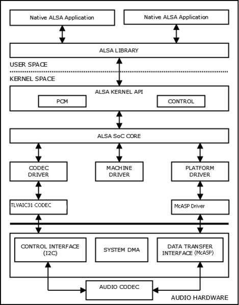
3.2.2.1.2. Software Architecture
All the hardware components are exposed to userspace applications using the Linux ALSA (Advanced Linux Sound Architecture) framework, which allows control and configuration of the hardware through common APIs. For more details check the links below.
Within the kernel there are separate drivers for each component. For each
board a sound-card instance is created, usually using the sound {}
device tree node, that links together various components like different McASP
instances to a codec or an HDMI bridge.
3.2.2.1.3. McASP Configuration
TI EVMs include a default McASP configuration in the device tree that defines the sound topology connecting McASP to the onboard codec(s). For custom designs using a different sound topology—such as different codec connections or a different codec—the McASP configuration parameters described in this section can be modified accordingly in the device tree.
The Multichannel Audio Serial Port (McASP) is a highly configurable audio interface that supports various audio protocols including I2S, TDM, and S/PDIF, and a flexible clocking scheme, which allows for complete independence between the receive and transmit ports.
McASP serializers are connected to data pins, referred to as AXR pins. The name stands for “Audio Transmit/Receive” (AXR), reflecting the fact that any McASP data pin can be configured to function as either an input or an output. As such, the terms “serializer” and “AXR pin” are used interchangeably throughout this documentation.
3.2.2.1.3.1. Device Tree Properties
McASP nodes are typically defined in the SoC-level device tree (.dtsi) first with
base properties like compatible, reg, interrupts, and dmas,
which stay the same regardless of audio configuration.
Board-level device trees then customize the McASP configuration using the properties below. Together they form the complete McASP node definition.
The following table briefly describes the McASP-specific properties configured in board-level device trees:
Property |
Type |
Required |
Description |
|---|---|---|---|
op-mode |
uint32 |
Yes |
Operation mode:
• 0 for I2S/TDM mode
• 1 for DIT mode (Transmitter-only mode for self-encoding formats like S/PDIF)
|
tdm-slots |
uint32 |
Yes, for I2S/TDM mode |
Number of TDM slots for TX (and RX if
tdm-slots-rx not specified). Range: 2-32.Ignored in DIT mode.
|
auxclk-fs-ratio |
uint32 |
No 1 |
A fixed multiplier to sampling rate (𝑓s) for a given AUXCLK frequency for TX (and RX if
auxclk-fs-ratio-rx not specified).1 If not specified, dividers are calculated from
.set_sysclk via the ASoC machine driver. (For common machine driver such as simple-audio-card or audio-graph-card, this is set via the system-clock-frequency = <> property in the DAI link).Only applicable when McASP is the master which produces the bit clock.
See Configuration Guidelines for details on usage and calculation.
|
serial-dir |
uint32 array |
Yes |
Serializer pin configuration.
For each AXR pin:
0 = Inactive,
1 = TX,
2 = RX.
Must include all AXR pins available on the McASP instance.
|
ti,async-mode |
boolean |
No |
Enables independent TX and RX clocking, allowing different sample rates (𝑓s) and bits per frame for playback and capture.
Ignored in DIT mode.
|
tdm-slots-rx |
uint32 |
No |
Number of TDM slots for RX, allowing independent RX slot count. Range: 2-32.
Requires
ti,async-mode. |
auxclk-fs-ratio-rx |
uint32 |
No |
Multiplier to sampling rate for a given AUXCLK frequency for RX.
Requires
ti,async-mode. |
tx-num-evt |
uint32 |
No |
WFIFO threshold for TX. Enables TX FIFO buffering when non-zero. Disabled by default. |
rx-num-evt |
uint32 |
No |
RFIFO threshold for RX. Enables RX FIFO buffering when non-zero. Disabled by default. |
Note
For more detail, refer to davinci-mcasp-audio.yaml and davinci-mcasp-audio.txt in the Linux kernel source.
3.2.2.1.3.2. Capabilities Overview
The McASP driver supports multiple audio protocols and operational modes:
Operation Modes:
I2S/TDM Mode (op-mode = 0)
Supports 2 to 32 TDM slots (channels)
Full-duplex operation (simultaneous TX and RX)
Can operate in synchronous or asynchronous mode
DIT Mode (op-mode = 1)
Transmit-only operation
Hardware-generated S/PDIF encoding
The
tdm-slots,ti,async-modeproperties are ignoredOnly inactive or TX serializers (values 0, 1) should be configured in
serial-dir
Clock Modes:
Synchronous Mode (default): TX and RX share the same bit clock and frame sync signals, requiring identical sample rates and bits per frame for both directions
Suited for simple, single-codec designs where ADC and DAC bit clocks and frame sync need to be synchronized
Asynchronous Mode (
ti,async-mode): Independent TX and RX clocking, allowing different sample rates, bits per frame, and TDM slot counts for playback and captureEnables simultaneous playback and capture with independent audio settings
Allows flexibility in multi-sound topology designs with various ASoC codec-class drivers connected to the same McASP instance
Important
.symmetric_rate should not be set in the codec driver’s snd_soc_dai_driver struct. Otherwise, opening streams with different audio settings will fail with errors similar to the following:[ 146.186314] davinci-mcasp.0-pcmdevice-codec: ASoC: unmatched rate symmetry: 2b20000.au
dio-controller:44100 - soc_pcm_params_symmetry:48000
[ 146.187012] davinci-mcasp.0-pcmdevice-codec: ASoC: error at __soc_pcm_hw_params on dav
inci-mcasp.0-pcmdevice-codec: -22
arecord: set_params:1456: Unable to install hw params:
...
Key Features:
Multiple serializers (up to 16) for multi-channel audio
Configurable McASP FIFO buffering (tx-num-evt, rx-num-evt)
Fixed clock generation with auxclk-fs-ratio or dynamic machine driver sysclk settings
Support for master and slave clock modes (via DAI link configuration)
3.2.2.1.3.3. Configuration Scenarios
The examples below show typical board-level McASP configurations. Base properties
like compatible, reg, interrupts, and dmas are inherited from the
SoC-level dtsi file and are not shown here.
I2S/TDM Mode - Synchronous, Stereo (2 slots)
For stereo audio (2 TDM slots) with synchronized TX/RX clocking:
 /* Example from AM62x-SK (k3-am62x-sk-common.dtsi) */
 &mcasp1 {
    status = "okay";
    #sound-dai-cells = <0>;

    pinctrl-names = "default";
    pinctrl-0 = <&main_mcasp1_pins_default>;

    op-mode = <0>;          /* MCASP_IIS_MODE */
    tdm-slots = <2>;
    auxclk-fs-ratio = <256>;
    serial-dir = <  /* 0: INACTIVE, 1: TX, 2: RX */
          1 0 2 0
          0 0 0 0
          0 0 0 0
          0 0 0 0
    >;
};
I2S/TDM Mode - Synchronous, Multiple TX Serializers
For stereo audio (2 TDM slots) with multiple TX serializers and auxclk-fs-ratio (synchronized TX/RX clocking):
/* Example from J721S2 (k3-j721s2-common-proc-board.dts) */
&mcasp4 {
   status = "okay";
   #sound-dai-cells = <0>;

   pinctrl-names = "default";
   pinctrl-0 = <&mcasp4_pins_default>;

   op-mode = <0>;          /* MCASP_IIS_MODE */
   tdm-slots = <2>;
   auxclk-fs-ratio = <256>;
   serial-dir = <    /* 0: INACTIVE, 1: TX, 2: RX */
      0 2 1 1
      0 0 0 0
      0 0 0 0
      0 0 0 0
   >;
};
I2S/TDM Mode - Asynchronous (Independent TX/RX)
For I2S/TDM mode with asynchronous clocking, enabling independent TX and RX configurations with different slot counts and sample rates. This contrasts with the synchronous I2S/TDM modes above where TX and RX share the same clocking:
/* Example from AM62D-EVM (k3-am62d2-evm.dts) */
&mcasp2 {
   status = "okay";
   #sound-dai-cells = <0>;

   pinctrl-names = "default";
   pinctrl-0 = <&main_mcasp2_pins_default>;

   auxclk-fs-ratio = <2177>;
   op-mode = <0>;          /* MCASP_IIS_MODE */
   tdm-slots = <2>;        /* DAC Codec configured for stereo playback */
   tdm-slots-rx = <4>;     /* ADC Codec configured for 4-channel capture */
   ti,async-mode;
   serial-dir = <    /* 0: INACTIVE, 1: TX, 2: RX */
         1 1 0 1
         1 0 0 0
         0 0 0 0
         0 0 2 0
   >;
};
DIT Mode (S/PDIF)
For S/PDIF digital audio output (transmit-only):
/* Example from OMAP4 device (omap4-l4-abe.dtsi) */
&mcasp0 {
   status = "okay";
   #sound-dai-cells = <0>;

   pinctrl-names = "default";
   pinctrl-0 = <&main_mcasp0_pins_default>;

   op-mode = <1>;    /* MCASP_DIT_MODE */
   serial-dir = < 1 >;
};
3.2.2.1.3.4. Configuration Guidelines
This section provides rules and guidelines when configuring certain McASP device tree properties.
auxclk-fs-ratio
This property defines the ratio between the AUXCLK (reference clock) and the sampling rate, as a means to statically configure its internal clock dividers. Giving a hint to the driver to pick the specific sampling rate whenever possible at runtime.
Alternatively, a fixed clock source frequency can be specified via the DAI-link property
system-clock-frequency = <> or via a custom machine driver’s .set_sysclk() callback,
allowing the driver to dynamically calculate dividers for any McASP-supported sampling rate.
Either or both properties may be defined. But at least one must be provided: auxclk-fs-ratio to specify the clock divider, or system-clock-frequency to specify the reference clock frequency directly.
When using auxclk-fs-ratio, calculate the ratio as follows:
For example, given a desired sampling rate of 44.1kHz with a 96MHz AUXCLK, the auxclk-fs-ratio would be: \(96000000 / 44100 = 2177\). This ratio is also applicable to other standard sampling rates McASP supports, as long as the produced bit clock is within acceptable tolerance.
The same applies to auxclk-fs-ratio-rx.
Refer to the Runtime Behavior section below for tolerance calculation details.
serial-dir
The serial-dir array size must match the hardware (e.g., 16 AXR pins for McASP0 means array must have 16 entries).
Each McASP instance may have up to 16 AXR pins, please refer to device-specific data sheet and TRM.
serial-dir = <  /* 0: INACTIVE, 1: TX, 2: RX */
      1 0 2 0  /* AXR0-3:  TX, Inactive, RX, Inactive */
      0 0 0 0  /* AXR4-7:  All inactive */
      0 0 0 0  /* AXR8-11: All inactive */
      0 0 0 0  /* AXR12-15: All inactive */
>;
3.2.2.1.3.5. Codec Integration
The McASP configuration described above defines the hardware interface. To create a functional audio device, the McASP node needs to be connected to codec class driver(s) via a sound card definition in the device tree.
The simple-audio-card is a generic machine driver and establishes Digital Audio Interface (DAI) links that connect the McASP (CPU-side) to codec(s). These DAI links operate within the ASoC framework, which constitutes part of the ALSA stack. Most TI EVMs use simple-audio-card for its simplicity, though audio-graph-card or custom machine drivers are also supported. All DAI link properties McASP relies on are part of the generic ASoC framework, not specific to any particular machine driver.
The DAI link configuration provides the following intrinsics to the McASP driver:
Link McASP instance(s) to codec instance(s)
Mapping of McASP serializers to DAI links
e.g., McASP assumes the first TX AXR pin is mapped to the first playback-enabled DAI link and outputs data to the first available TX TDM slot; see Channel Mapping
Master/slave clocking roles for bit clock and frame sync signals
If McASP is the master,
system-clock-direction-outmust be declared in the CPU DAI for McASP to generate clocks
Data alignment format
e.g., “dsp_a”, “dsp_b”, “i2s”
Polarity of bit clock and frame sync signals via
bitclock-inversionandframe-inversionOptional dai-link properties:
system-clock-frequencydai-tdm-slot-widthdai-tdm-slot-numdai-tdm-slot-tx-maskdai-tdm-slot-rx-mask
Attention
Due to ASoC and driver limitations, the data alignment format must remain the same for every DAI link connected to the same McASP node, even in asynchronous mode where the hardware is capable of having independent playback and capture settings.
3.2.2.1.3.5.1. Optional dai-link Properties
system-clock-frequency (Type = uint32)
When McASP is the bit clock master, this property provides a fixed reference clock frequency to the McASP driver, refer to the Runtime Behavior section below.
dai-tdm-slot-width (Type = uint32)
In the McASP driver logic, audio bit widths are dynamically configured at runtime, unless constrained by the optional dai-tdm-slot-width property. When specified, this property limits the hardware TDM slot width on the bus, restricting the maximum format width (bit depth) while still allowing dynamic selection within that constraint.
For instance, setting dai-tdm-slot-width = <24> allows audio bit depth of 8, 16, or 24 per sample, but not 32 bits.
On the specifics of how the driver handles audio format negotiation at runtime, refer to the Runtime Behavior section below.
dai-tdm-slot-num (Type = uint32)
Applying dai-tdm-slot-num by itself is not advised, as McASP already derives the TDM slot count from tdm-slots or tdm-slots-rx properties in the McASP device tree node.
The property is to be used in conjunction with dai-tdm-slot-width to accommodate the standard ASoC API.
Attention
dai-tdm-slot-width property to a DAI link, ensure dai-tdm-slot-num is also provided, to avoid slot count mismatches set by ASoC API.dai-tdm-slot-num must match the tdm-slots defined in the McASP node.dai-tdm-slot-num must match the tdm-slots, or tdm-slots-rx if supplied.dai-tdm-slot-tx-mask and dai-tdm-slot-rx-mask (Type = uint32 array)
dai-tdm-slot-tx-mask and dai-tdm-slot-rx-mask allow masking out specific TDM slots on the bus for TX stream and RX stream, respectively, providing finer control over which slots are active for audio data transfer.
The properties are type uint32 array, where each bit represents a TDM slot on the bus. A bit value of 1 indicates the corresponding slot is active, while 0 means inactive. The size of the array must match the number of TDM slots defined in the McASP node.
playback-only and capture-only (Type = boolean)
A DAI link is deemed playback-enabled if both CPU (McASP) and codec DAI support playback (TX), and capture-enabled if both support capture (RX).
Since McASP supports both TX and RX, the playback-only and capture-only properties can restrict a DAI link’s direction when the codec driver also supports both directions.
The restricted direction will not be exposed as an ALSA PCM subdevice.
Tip
The following example illustrate the optional dai-link properties discussed above.
sound0 {
   compatible = "simple-audio-card";
   simple-audio-card,name = "Demonstration";

   simple-audio-card,dai-link@0 {
      format = "dsp_a";
      bitclock-master = <&cpu_dai>;
      frame-master = <&cpu_dai>;

      cpu_dai: cpu {
            sound-dai = <&mcasp0>;
            system-clock-direction-out;

            /* Configuration for 4 slots, each 24 bits wide max */
            /* tdm-slots = <4>; in McASP node */
            dai-tdm-slot-num = <4>;
            dai-tdm-slot-width = <24>;

            /* Bitmask to enable specific slots (e.g., 3rd tdm slot is inactive) */
            dai-tdm-slot-tx-mask = <1 1 0 1>;
            dai-tdm-slot-rx-mask = <1 1 0 1>;
      };

      codec {
            sound-dai = <&tlv320aic32x4>;

            /* Assume codec driver also implements the interface */
            dai-tdm-slot-num = <4>;
            dai-tdm-slot-width = <24>;
      };
   };
};
3.2.2.1.3.5.2. Audio Card Examples
Single Codec
For simple stereo configurations with one codec, a single DAI link suffices:
sound0 {
   compatible = "simple-audio-card";
   simple-audio-card,name = "AM62x-SKEVM";
   simple-audio-card,format = "i2s";

   simple-audio-card,cpu {
      sound-dai = <&mcasp1>;
   };

   simple-audio-card,codec {
      sound-dai = <&tlv320aic3106>;
   };
};
In this single codec configuration:
ti,async-modeshould be disabled (synchronous mode) in McASP device tree node since playback and capture share the same codec and require identical clock settings
Multiple Codecs
When using multiple codecs, define separate DAI links for each codec. The following syntax allows separate configurations for each DAI link:
/* Example from AM62D-EVM (k3-am62d2-evm.dts) */
sound0 {
   compatible = "simple-audio-card";
   simple-audio-card,name = "AM62D2-EVM";

   /* First DAI, McASP in master mode */
   simple-audio-card,dai-link@0 {
      format = "dsp_a";
      bitclock-master = <&master0>;
      frame-master = <&master0>;

      master0: cpu {
            sound-dai = <&mcasp2>;
            system-clock-direction-out;
      };

      codec@0 {
            sound-dai = <&pcm6240>;
      };
   };

   /* Second DAI, McASP in master mode */
   simple-audio-card,dai-link@1 {
      format = "dsp_a";
      bitclock-master = <&master1>;
      frame-master = <&master1>;

      master1: cpu {
            sound-dai = <&mcasp2>;
            system-clock-direction-out;
      };

      codec@1 {
            sound-dai = <&tad5212_dac1>;
            playback-only;
      };
   };

   /* Additional dai-link@2, @3, @4 for more codecs... */
};
In this multi-codec configuration:
Each DAI link connects the same McASP instance to different codecs and maps serializers/AXRs accordingly
It is recommended to enable
ti,async-modein the McASP device tree node to allow more flexibility with independent TX/RX clockingThe
bitclock-masterandframe-masterproperties specify which device (CPU or codec) drives the bit clock and frame sync signalssystem-clock-direction-outis required for McASP to generate clocks, which is required when McASP is driving the signals in master modeSince McASP is in master mode,
auxclk-fs-ratioshould be defined in the McASP node, otherwisesystem-clock-frequencymust be set in the DAI link to provide a fixed clock source
For more information on DAI link configuration and ASoC machine drivers, refer to ALSA links in the Additional Information section below.
3.2.2.1.3.6. Runtime Behavior
The McASP driver makes dynamic runtime decisions when handling audio streams, including serializer activation, channel-to-slot mapping, and supported audio formats. These behaviors are determined by the interaction between hardware capabilities and parameters requested by userspace through the ALSA framework.
Note
The runtime behaviors described in this section apply to I2S/TDM mode (op-mode = 0) only.
DIT mode (op-mode = 1) has fixed S/PDIF encoding behavior per specification.
3.2.2.1.3.6.1. Channel Mapping
When a playback or capture stream is opened, the ALSA framework passes the requested number of audio channels from the userspace application to the McASP driver.
The driver activates TX or RX serializers (AXR pins) in the order they appear in the serial-dir
device tree property. For each serializer, the driver maps channels to available TDM slots sequentially.
If dai-tdm-slot-tx-mask or dai-tdm-slot-rx-mask are configured, disabled slots are skipped.
This process continues across multiple serializers until all requested channels are mapped.
Unused TDM slots and AXR pins remain inactive.
The total TDM slot count on the bus (frame sync period) is always preserved as defined
by tdm-slots or tdm-slots-rx, regardless of how many channels are actively used.
If the requested channels exceed the available capacity (\(active\_serializers \times slots\_per\_serializer\)), the driver rejects the stream with an error.
3.2.2.1.3.6.2. Sample Rate and Bit Depth
Note
This section only pertains to McASP configured as the bit clock master. When McASP is in slave mode, it accepts whatever combinations the codec provides without imposing constraints.
When a stream is opened and McASP is in master mode, the driver evaluates which sample rate and bit depth combinations can be supported based on its ability to generate the required bit clock frequency within ±1000 ppm tolerance (0.1%).
The driver uses auxclk-fs-ratio (if defined) to calculate the expected reference clock
frequency as rate × ratio for each sampling rate, and/or uses a fixed clock source frequency
from system-clock-frequency/.set_sysclk() for all rates. In both cases, it calculates
dividers to determine which bit clock frequencies can be achieved within tolerance.
\(error_{ppm} = \frac{actual\_freq - target\_freq}{target\_freq} \times 10^6\)
Only combinations that can be accurately generated are provided as supported formats, and ALSA subsequently selects the best configuration for the userspace application.
To support a specific sample rate and bit depth combination, ensure that:
The
auxclk-fs-ratioproperty or machine driver’s.set_sysclk()configuration allows the McASP to generate the required bit clock frequency within toleranceThe codec supports the desired combination
If the source audio format differs, one may configure explicit resampling via
~/.asoundrcor/etc/asound.confALSA config file in userspace.
3.2.2.1.4. Generic commands and instructions
Most of the boards have simple audio setup which means we have one sound card with one playback and one capture PCM. To list the available sound cards and PCMs for playback:
aplay -l
To list the available sound cards and PCMs for capture:
arecord -l
For McASP-based sound card, each DAI link instance is represented as a separate subdevice.
In most cases -Dplughw:0,0 is the device we want to use for audio
but in case we have several audio devices (onboard + USB for example)
one needs to specify which device to use for audio:
To play audio on card0’s PCM0 and let ALSA to decide if resampling is needed:
aplay -Dplughw:0,0 <path to wav file>
To record audio to a file:
arecord -Dplughw:0,0 -t wav <path to wav file>
To test full duplex audio (play back the recorded audio w/o intermediate file):
arecord -Dplughw:0,0 | aplay -Dplughw:0,0
To request specific audio format to be used for playback/capture take a look
at the help of aplay/arecord. For example, one can specify the format with -f,
the sampling rate with -r, or the number of channels with -c.
In this case, one should open the hw device (not the plughw) via -Dhw:0,0.
For example, record 48KHz, stereo 16bit audio:
arecord -Dhw:0,0 -fdat -t wav record_48K_stereo_16bit.wav
Or to record 96KHz, stereo 24bit audio:
arecord -Dhw:0,0 -fS24_LE -c2 -r96000 -t wav record_96K_stereo_24bit.wav
It is a good practice to save the mixer settings found to be good and reload them after every boot (if your distribution is not doing this already)
Set the mixers for the board with amixer, alsamixer
alsactl -f board.aconf store
After booting up the board it can be restored with a single command:
alsactl -f board.aconf restore
3.2.2.1.5. Board-specific instructions
SK-AM62x, SK-AM62Ax, SK-AM62Px, J722S-EVM
Kernel config
Device Drivers  --->
  Sound card support  --->
    Advanced Linux Sound Architecture  --->
      ALSA for SoC audio support  --->
        Audio support for Texas Instruments SoCs  --->
          <*> Multichannel Audio Serial Port (McASP) support
        CODEC drivers  --->
          <*> Texas Instruments TLV320AIC3x CODECs
        <*>   ASoC Simple sound card support
User space
The hardware defaults are correct for audio playback, the routing is OK and the volume is ‘adequate’ but in case the volume is not correct:
amixer sset PCM 90%
For recording using the mic pin on the 3.5mm jack, you will need to unmute MIC3R on the codec, and increase the capture volume:
amixer sset 'Left PGA Mixer Mic3R' on
amixer sset 'Right PGA Mixer Mic3R' on
amixer sset PGA 90%
To switch to using HDMI for playback you can refer to: How to playback audio over HDMI.
3.2.2.1.6. Potential issues
In case of XRUN (under or overrun)
Increase the buffer size (ALSA buffer and period size)
Try to cache the file to be played in memory
Try to use application which uses threads for interacting with ALSA and with the filesystem
3.2.2.1.7. Additional Information
ALSA links
Using ALSA Audio API Author: Paul Davis
Software Help
Audio hardware codecs
McASP Documentation